A 30 ton gantry crane is one of the most commonly used lifting systems in industrial environments such as steel fabrication workshops, precast concrete plants, warehouses, and logistics yards. Although the mechanical structure is robust, most operational failures in real projects do not come from steel structures—they come from the electrical system.
In practice, electrical faults rarely appear as a single obvious failure. Instead, they usually present as symptoms: intermittent stopping, slow response, partial movement, or unexpected tripping. That is why diagnosis needs a logical approach rather than random component replacement.
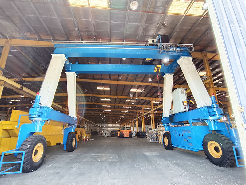
This guide explains a practical step-by-step method used by field engineers, and the same logic also applies to larger systems such as rubber tyred gantry cranes and rail mounted gantry cranes used in ports and container yards.
1. Start from the symptom, not the component
The first mistake many technicians make is immediately focusing on parts like motors or VFDs. In reality, the correct starting point is always the symptom.
For example:
- If the crane does not move at all → likely power or control loop issue
- If only one motion fails (trolley or hoist) → localized control or drive issue
- If operation stops mid-cycle → protection system or signal interruption
Before opening any electrical cabinet, it is important to observe:
- What exactly was being done when the fault occurred
- Whether the fault is consistent or random
- Whether any alarm code is displayed
This basic information often reduces troubleshooting time by half.
2. Check whether the crane is truly receiving stable power
In many 30 ton gantry crane systems, especially those used outdoors, unstable power supply is the root cause of repeated faults. This is even more common in rubber tyred gantry crane configurations where power is delivered through cable reels or hybrid supply systems.
The inspection should focus on:
- Phase balance stability
- Voltage drop under load
- Cable reel or festoon movement condition
- Terminal tightness at main incoming supply
A very common real-world scenario is this: the crane works normally at light load, but trips under full load. This is often not a “motor problem” but a voltage drop issue along the supply path.
3. Verify the control chain before touching the drive system
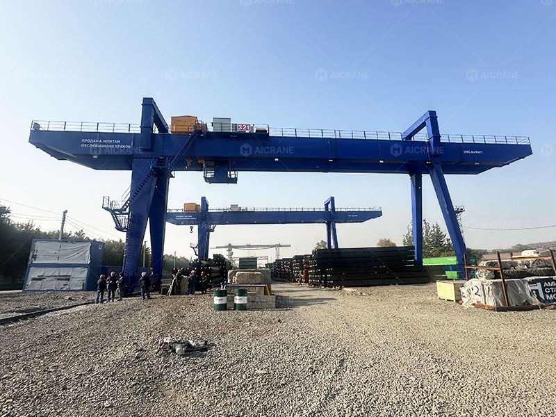
Once power is confirmed stable, the next layer is the control system. Modern cranes often use PLC-based control logic, especially in double girder gantry crane systems used in structured production lines.
At this stage, engineers typically check:
- Emergency stop loop continuity
- Control transformer output
- Relay switching response
- PLC input/output signal status
A useful way to think about this stage is simple:
If the crane is “not listening”, the problem is usually in the control signal, not the power circuit.
One common mistake is assuming a VFD fault when the actual issue is a broken signal wire or a faulty relay in the control circuit.
4. Then move to the drive system (VFD or inverter)
Only after confirming power and control integrity should the VFD system be analyzed.
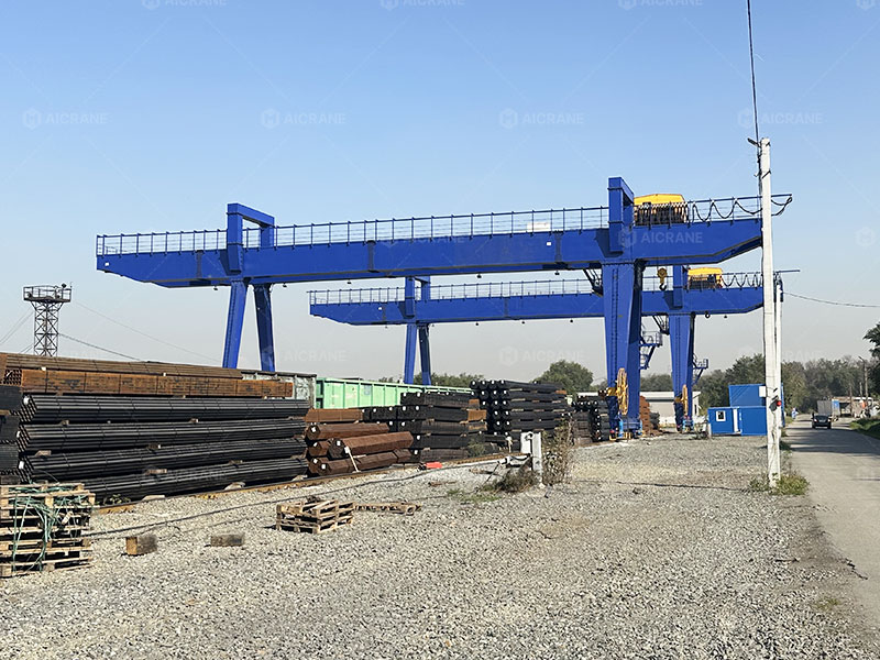
In rail mounted gantry cranes and container handling cranes, VFDs are heavily loaded due to frequent start-stop cycles and high torque demands.
Typical fault codes include:
- Overcurrent (OC): often mechanical resistance or motor overload
- Overvoltage (OV): braking resistor or power regeneration issue
- Undervoltage (UV): unstable supply or cable loss
- Overheat (OH): ventilation or fan failure
Instead of immediately resetting the drive, it is more important to ask:
“What caused the drive to protect itself?”
A VFD is usually not the root problem—it is a protection response.
5. Motor issues are usually secondary, not primary
In field experience, motors are often blamed too early. However, most motor failures are consequences, not causes.
Before concluding motor damage, check:
- Insulation resistance stability
- Whether all phases are balanced
- Whether the brake is fully releasing
- Whether the motor is physically overloaded or blocked
In heavy duty gantry crane applications, especially in steel mills or precast yards, motors often fail due to long-term overload rather than sudden defects.
A key point many technicians miss is that a “non-starting motor” is often held mechanically by a brake issue rather than an electrical failure.
6. Do not ignore safety devices and limit switches
Limit switches and safety interlocks are small components, but they can completely stop crane operation.
In workshop gantry crane systems, for example, a misaligned limit switch can disable motion even when everything else is normal.
Key points to check:
- Hoist upper/lower limit switches
- Travel end-stop switches
- Anti-collision sensors (if installed)
- Overload protection system
A single false signal in any of these devices can cut the entire control loop.
7. Brake system electrical control is often overlooked
Another frequent hidden issue is brake control failure.
Even if the motor runs, if the brake does not release properly, the crane will appear “dead” under load.
Check:
- Brake rectifier output
- Coil voltage supply
- Air gap condition
- Mechanical sticking of brake disc
This issue is particularly common in cranes with frequent cycling, such as container gantry cranes or high-duty workshop cranes.
8. Re-check the system as a whole before final judgment
At this point, most faults can already be isolated. The final step is not technical—it is logical validation.
Ask:
- Does each subsystem behave correctly independently?
- Does the fault appear under specific load or motion only?
- Is there any pattern (time, temperature, load)?
This step often reveals hidden issues like:
- Loose connectors that fail under vibration
- Heat-related intermittent faults
- Signal interference in control lines
9. Final testing under controlled load
After repairs, the crane should never return directly to full operation.
A proper test sequence includes:
- No-load full motion test
- Partial load test (around 30–50%)
- Full load test under controlled conditions
- Emergency stop and limit switch verification
Only after stable operation in all conditions should the crane be returned to production use.
Conclusion
Electrical fault diagnosis in a 30 ton gantry crane is not about checking parts one by one—it is about following a logical chain: power → control → drive → motor → safety system.
Most failures are not sudden hardware breakdowns but the result of signal loss, unstable power, or protective responses triggered by underlying mechanical or electrical stress.
The same diagnostic logic applies across different crane systems, whether it is a rubber tyred gantry crane in a yard, a rail mounted gantry crane in a port, or a double girder gantry crane in a factory workshop.
A structured approach not only reduces downtime but also prevents unnecessary component replacement, making maintenance faster, safer, and more cost-effective.